The Allegro-patented PCB Q-Rift designs can more than double the maximum allowable current, solving major problems for engineers looking for a simple, high-power-density solution
When designing and integrating new sensing elements into an application, the desire to reduce the cost and increase the power density of the system is a common theme that typically raises questions about the design of the core and the sensing elements. For example, traditional high-current sensors use a ferrous C-core to concentrate the magnetic field to a single Hall plate array on a sensor IC, while new differential Hall sensing technologies enable removal of all ferrous concentrators.
The new, truly coreless approach is a well-known solution in applications for extended electrified vehicles (xEVs), and it is commonly used for mid- to high-power xEV traction inverters, where current can reach up to ~1000 A through a busbar. By running current though the copper within the printed circuit board (PCB), the same coreless, differential Hall technology can also be leveraged in lower-power applications, limited by the maximum current that can be run through the PCB. Compared to classic PCB notch designs, Allegro-patented PCB Q-Rift designs can more than double the maximum allowable current – ranging up to 300 A or a peak of 400 A – to serve a wider range of lower-power applications.
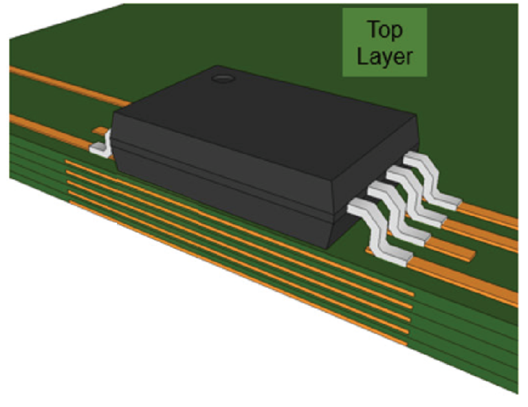
The Q-Rift PCB design from Allegro MicroSystems solves two major problems for engineers looking for a simple, high-power-density solution. Firstly, it offers plug-and-play simplicity with minimal calibration. The Q-Rift design changes the geometries of each of the copper traces within the PCB directly below the sensor IC package. This not only permits the magnetic field to be properly coupled with the sensing elements but also allows specific designs that substantially reduce tolerance misplacement caused by pick-and-place manufacturing processes. This creates an easier plug-and-play solution that greatly simplifies or eliminates end-of-line calibration steps.
The Q-Rift PCB design also offers thermal handling with varying thickness/layer count. By optimizing all copper layers of the PCB, more copper can be added to increase the conductor cross-sectional area. This allows the PCB to thermally handle approximately 250 A, and up to 350 A depending on the number of layers and thickness of each layer. The Allegro Q-Rift PCB employs a design rule that can be applied to various board thicknesses and layer count. To support engineers with initial validation of these sensing solution concepts, three Allegro PCB evaluation board designs for <400 A current sensing applications were compared, as shown in the summary table below, and tests were performed using:
Classic Notch PCB Designed for < 150 A all copper layers follow the same notched geometry.
Q-Rift AC Designed for < 400 A with higher bandwidth limits.
Q-Rift DC Designed for < 400 A with lower bandwidth limits.

The summary table above shows continuous and peak current ranges, position tolerance errors, and AC performance. The additional copper in the Q-Rift design results in better thermal performance, as shown in the comparison of PCB designs at right.
The Q-Rift (blue) and notched (red) designs receive a continuous current of 155 A, applied at room temperature. The temperature of the notched PCB reaches a plateau of 80°C after 5 minutes, whereas the temperature increase of the Q-Rift board is negligible. When the continuous current increases to 300 A with the DC Q-Rift, the temperature does not exceed 90°C at room temperature.
These thermal measurements demonstrate that the Q-Rift PCB can be operated at a much higher current than the notched PCB. As shown in the preceding examples and explanations, by implementing an Allegro Q-Rift PCB, designers can more easily achieve objectives for high-power-density automotive applications – such as 48 or 400 V traction inverter systems, various DC-DC converters, power distribution units, or various green energy applications.


