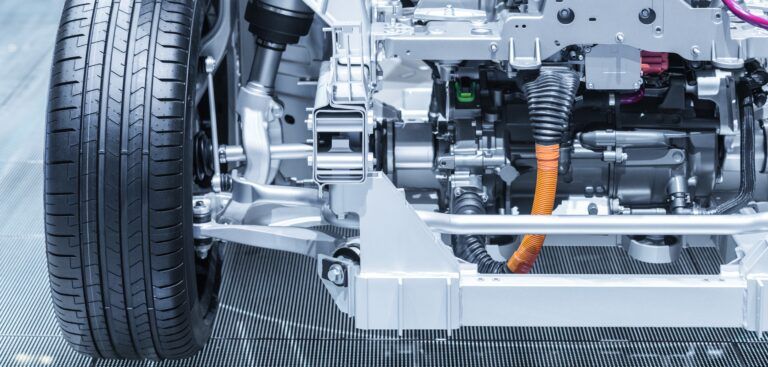
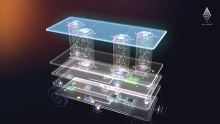
Over the past decade, most transportation markets, from automotive, to military, aircraft, and even space systems have seen a tremendous surge of interest in hybrid and electric vehicle technology. To gain the promised efficiency benefits and green profile of these vehicles, it is important to conduct driveline and component testing during design and manufacturing that is specially adapted to the particular nature of hybrid and electric vehicles.
Hybrid and electric drivetrains have several features that make testing them very different from the standard testing conducted on internal combustion (IC) only systems. Hybrid and electric systems use regenerative braking (where braking actually generates power that is returned to and stored in the vehicle’s battery for later use). This typically requires addition of fairly complex AC inverter technology, and often more complex transmissions.
In addition, these vehicles often have several module control units (MCU’s), essentially small onboard computers, which control the functions of such major subsystems as the engine, transmission, and charging system, among others. To properly test these components, the test system needs to be able to communicate with one or more of these units via a high speed in-vehicle networks. This changing technology and increased complexity requires a testing system very different, and more complex, than those used in IC-only systems.
The technology is out there to ensure proper testing and realization of the energy efficiency benefits promised by hybrid and electric vehicles. What’s more, the testing technology is itself energy efficient, reducing operations and maintenance costs and contributing to the vehicle’s overall environmental performance.
Types of Hybrid/EV driveline testing
Hybrid or electric driveline testing is conducted at several stages during the development of a vehicle, and each has an important role to play.
Engineering testing – design engineers need precise measurements
Accurate measurements are critical so design engineers can extract every bit of efficiency from their designs. Otherwise they will lose much of the advantage of using hybrid/electric technology. Most vehicles use 3-phase AC motors driven by inverter technology, so sophisticated power analyzers are needed to properly measure 3-phase AC power with a large amount of harmonic content. These test systems tend to be rather complex and are usually the most sophisticated, with many elements to be tested and coordinated.
In-process and end-of-line testing – manufacturers verify performance and safety
Manufacturing end-of-line testing is usually performed to verify that no defects were introduced in the manufacturing process, and that the components will perform to specifications. Typical tests include operational validation, quick performance testing, as well as rigorous testing to validate that high-voltage electrical systems are properly isolated, and are therefore safe to use in vehicles.
In-process testing may also be conducted to test partial assemblies along the production line. This improves manufacturing efficiency and significantly reduces the chance that faulty components will find their way into the finished product.
Quality control testing – motor users look for defects in incoming product
Quality control (QC) testing is usually done on a percentage of the components to verify that that they perform over the specified range, and are relatively free of defects. For example, a fork lift company may conduct QC testing on a shipment of imported electric motors that are scheduled to be placed inside their forklifts. They would use QC testing to verify that the shipment coming from their supplier performs as specified and will not experience high failure rates in the field. This type of test system is typically less complex, because it does not have to measure as many items, nor to the degree of accuracy, as those tested in engineering systems.
Regenerative braking
Hybrid or electric vehicles use 4-quadrant motor/inverter technology to either assist the engine (hybrid) or as the prime mover (electric vehicle). Four quadrant means that the electric motor can control velocity or torque in either direction − the motor can accelerate, run, and decelerate forward or backward.
During deceleration, the system uses regenerative braking, so the electric motor is used to slow the vehicle, and in the process becomes a generator, partially recapturing the energy of motion in the vehicle and restoring it to the battery. In hybrid systems, when stopping, slowing down, or idling, the engine is typically shut off and not burning fuel. At the same time, the electric motor again becomes a generator, partially recouping energy and storing it back in the battery. The engine is switched back on when needed to keep the vehicle moving, or to accelerate. During this time, the electric motor assists in accelerating the vehicle, using some of the recaptured electrical energy to reduce the load on the engine, and therefore reduce fuel consumption.
Using this recaptured power is the reason we can go longer between fillups and/or charges, leading to the improvements in fuel economy we are seeking. It is essential that the testing program used in designing and manufacturing the vehicles ensure that the powertrain is running efficiently and making the best use of this regenerative power.
Testing systems for hybrid or electric vehicles
Testing hybrid and electric vehicles is worlds apart from traditional internal combustion engine testing, which typically measures speed, torque, and a few temperatures, pressures, and flows. Very precise control of speed and torque is typically not required in testing internal combustion engines, so dynamometers used for standard combustion engine testing (for example, water brake and eddy current) were never designed to handle the types of precision required by hybrid or electric powertrains, nor can they test the regenerative (motoring) modes of operation.
Modern hybrid/EV test systems must provide all of the functionality of traditional systems, with the added ability to test high-power regenerative electrical drives, high voltage battery and charging systems, and communicating with any number of smart control modules (MCU’s).
Electrical system testing
For many larger hybrid/electric drivetrains, there is a strong trend toward using higher voltage, higher efficiency drive systems. Going from the traditional 12/24-volt DC electric system to one using 240 volts AC will typically require one-eighth or less of the current to deliver the same power. Not only is this more efficient, but it also requires much smaller/lighter wiring and smaller components to transfer the energy, leading to smaller, lighter, more energy efficient vehicles. Many current designs operate at 800 volts or more, making the vehicles even more efficient.
To conduct this type of testing, it is essential to use a 4-quadrant motoring dynamometer, which can simulate/test all modes of operation in a hybrid or electric vehicle. The ability to drive or load in either direction is exactly what is needed to test a system that itself operates in this manner. A standard dynamometer is just not capable of testing the system during braking, when it is in regenerative mode.
Creation of high-efficiency, AC powered systems typically involves the use of three-phase, inverter based technology to precisely control the electric motor(s) in the system. These systems tend to be very efficient, but also generate a great deal of harmonic distortion in the power output. So, in addition to the motoring dynamometer, a modern hybrid/EV test system typically includes a rather sophisticated three-phase power analyzer. This unit must be specifically designed to accurately measure high-power electrical values with a great deal of harmonic distortion present.
To meet the need for a system that can fully test hybrid and electric vehicle drive systems, SAKOR developed HybriDyne, a comprehensive test system for determining the performance, efficiency, and durability of all aspects of hybrid drivetrain systems, including electrical assist (parallel hybrid), diesel electric (serial hybrid), and fully-electric vehicle systems.
The HybriDyne integrates components of SAKOR’s DynoLAB powertrain and electric motor data acquisition and control systems. Coupled with one or more of its AccuDyne AC Motoring Dynamometers, and one or more precision power analyzers, the modular HybriDyne can test individual mechanical and/or electrical components, integrated sub-assemblies and complete drivetrains with a single system.
High voltage battery simulation and testing
A critical element of modern hybrid or electrical vehicles is the high-voltage battery and charging system. To accurately test a high voltage hybrid or electric drivetrain, you need to be able to provide precise, repeatable high-voltage DC power. Since battery performance changes over time depending upon their charge state, ambient conditions, and age, they are typically not acceptable for powering the DC components of a hybrid/EV test system. To achieve repeatable results you need a reliable DC power source. A standard off-the-shelf power supply will not work, because it cannot absorb power from the regenerative system. In fact, a standard power supply used with a regenerative system may be damaged or destroyed.
SAKOR solved this problem by developing a Solid State Battery Simulator/Test System specifically to test high-voltage hybrid vehicle batteries and simulate these batteries in an electric drivetrain environment.
At the heart of the system lies a high-efficiency, line-regenerative DC power source. During regenerative modes, absorbed power is regenerated back to the AC mains instead of being dissipated as waste heat, which is common practice among previous generation testing systems. This innovative method provides much greater power efficiency and measurably reduces overall operating costs.
Coupled with the DynoLAB, the Solid State Battery Simulator/Tester accurately simulates the response of the high-voltage battery in real-world conditions. However, since it is not subject to a variable charge state, it provides repeatable results, test after test. This same unit, when operated as a battery tester, subjects the battery to the same charge/discharge profile as it would encounter in an actual vehicle on an actual road course.
One of the advantages of using the AC dynamometer with a regenerative DC power source is that when the two are coupled together, the power absorbed by one unit can be re-circulated back to the other unit within the test system. This greatly reduces the power drawn from the AC mains (by as much as 85% to 90%), and therefore significantly reduces total cost of operation. This is an extremely energy efficient configuration, that can easily pay for itself, often many times over, during the life of the test system. Very low maintenance requirements also contribute significantly to lowering operating costs.
Communication with control modules
Communication with individual control modules (MCU’s) is another feature that has to be built in to testing systems for hybrid or electric vehicles. In the past, the engine was primarily controlled using the throttle and ignition. Now, engines have an engine control unit (ECU), the vehicle will likely have a separate MCU that controls the electric drive, and may have separate units for controlling the transmission and/or charging systems. These units typically communicate commands and/or data between themselves via a high-speed vehicle networks, such as CAN, LIN, FlexRay, etc.
To properly test this complex drivetrain configuration, the test system must be able to communicate with these control units simultaneously and efficiently. The DynoLAB system was designed to integrate all of these separate units into a single, coordinated test platform.
There is great excitement in the automotive, heavy equipment, military, and aerospace industries over the promise of improved environmental performance of hybrid and electrical vehicles. To achieve that promise, driveline testing programs must be adopted that meet the needs of this new and emerging technology.


